Deciphering HPC’s Technology: The 10 Flash Code

HPC strives to elevate the consumer experience. At each point of service, we put our customers first. HPC’s Tech talks aim to educate and empower our clientele. Informing consumers how to best maintain their fire appliances will extend the life of their designs, ensuring that they will stand the test of time. For this Tech Talk, the HPC Fire Inspired team will review the meaning of the 10 Flash Code, as well as how to achieve proper resolution.
The 10 Flash Code
When a 10-flash code is present on the control module or the remote control, it is an indication of a circuit failure within the module. The technology is not able to tease out the specific failed circuit. To rectify this issue the control module will need to be replaced. Prior to replacement, it is recommended to check the voltage to ensure that it isn’t faulty to avoid damaging the newly installed control module.
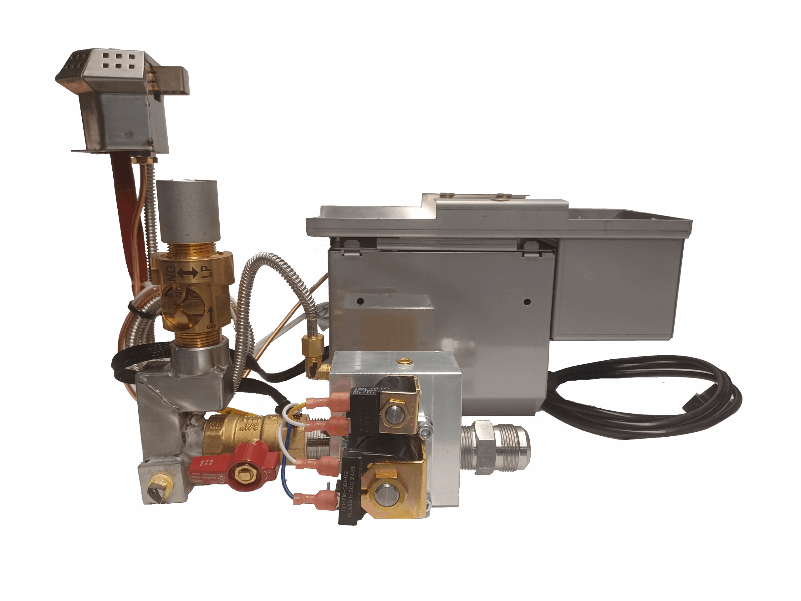
The Control Module- Voltage & Drainage Requirements
The control module is the brain of the system. It is powered by 24volts from the transformer on 120v unit or through a power supply for the low voltage units. The module monitors proper thermocouple and igniter operation as well as valve functions throughout unit. When the control module is damaged or has failed, there is no indication as to what has failed in the module.
Although there is no way to determine what has failed in the control module, there are a few external issues that can cause the damage. Improper voltage applied to the control module will result in damage to the circuitry in the module. Improper voltage will damage the module resulting in the 10 flash code.
Another instance that they control module can become damaged is due to lack of proper drainage in an enclosure. Without proper drainage, the valve control system may become engulfed by water due to outdoor elements. Excessive flooding will damage the module. While water mitigation is a large part of HPC Fire Inspired engineering, it is imperative to create proper drainage at the point of installation to protect the unit.
Deciphering & Rectifying the 10-Flash Code
To rectify the source of the issue the the control module will need to be replaced. Before the replacement is completed be sure to check voltage powering the module. On a 120v unit make sure the voltage out of the fuse holder to the module is no more than 30volts. A normal voltage reading powering the module from the fuse holder is about 26v-28v. A voltage reading above 30 volts will cause damage to the module.
On a 24v or 12v unit the wattage of the transformer or power supply must be verified. The electronic ignition control module must also be supplied with the proper wattage. The wattage or VA (volts x amps) rating must be verified. For example, the low voltage electronic ignition units will utilize 4 FLA (full load amps). To figure out the wattage multiply volts by amps, so 24 volts x 4 amps = 96 watts. Therefore, need 100 watts supplied to the module. In this instance, a 40VA or 40-watt transformer will cause damage to the module.
If these electrical requirements are verified then it can be determined that the control module failed, and the replacement repair can be completed. In addition, utilize HPC’s Trouble shooting feature highlighted on our smart apps. As always, contact HPC Fire Inspired Tech Team and our experts will walk you through steps to rectify the issue.
Customer Service
If you have any questions or concerns, please give us a call at 937-436-9800. Let our NFI certified technicians provide guidance around all your fire design needs.
Looking to learn more about HPC’s Electronic Ignition? Schedule an online or in person training with Chuck Parsons, HPC’s training and education manager.


